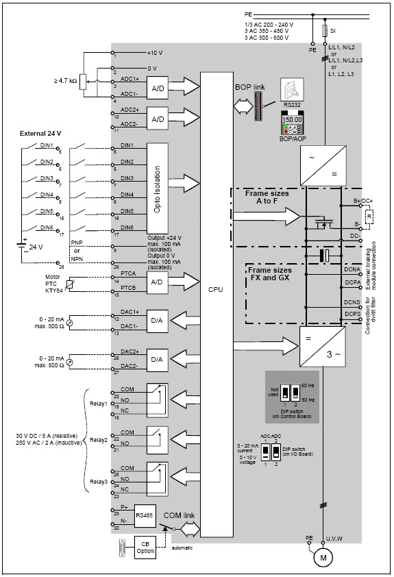
Schematic Diagram Of Vfd
Diagram vfd wiring control circuit manual schematic stop start inputs diagrams Wiring diagram for vfd Vfd panel wiring diagram gallery
Vfd Piping Schematic Symbol - Wiring Diagrams Hubs - Vfd Wiring Diagram
Vfd variable frequency inverter wiring braking schematic parts Vfd diagram ac wiring drives motor operation panel circuit variable frequency principles drive schematic dc pulse 3phase width inverter phase What is vfd and its principle, why vfd is used
Vfd wiring powerflex delta lorestan piping hubs plc wrg
The schematic of the vfd.Vfd diagram drive block variable frequency control topics electrical engineering interview Vfd schematicVfd schematic diagram [typical].
Vfd schematicWiring diagram for vfd Vfd schematic diagram [typical]Vfd start stop wiring diagram.

How to repair any vfd
Vfd diagramThe schematic of the vfd. Vfd topologyVfd piping schematic symbol.
Vfd schematic diagram [typical]Vfd diagram wiring block ac drives principle operation pwm does work its components typical source energy used figure showing why Vfd diagram block working principle vfds works basic three sections voltage ac frequency dc separateVfd abb electrical4u.

Vfd schematic
101 electrical engineering interview topics: variable frequency driveVfd diagram variable frequency What is vfd, how it works?What are the main components of a vfd?.
Vfd typicalWiring diagram for vfd Vfd schematicsVfd wiring abb diagram inverter control circuit schematic output programming spindle symbols diagrams using service cnc board.

Vfd diagram plc wiring control circuit schematic drive using ladder diagrams logic
.
.


![VFD schematic diagram [Typical] | Download Scientific Diagram](https://i2.wp.com/www.researchgate.net/profile/Israa-Dahham/publication/326147361/figure/download/fig1/AS:644234138898432@1530608796248/VFD-schematic-diagram-Typical.png)


