Skip to content

Demodulation Circuit Diagram

A Block Diagram of the Demodulator Circuit. | Download Scientific Diagram

Simple fm demodulator circuit diagram The demodulation circuits Bpsk demodulator waveform

A Block Diagram of the Demodulator Circuit. | Download Scientific Diagram

Circuit diagram for the demodulator: the demodulator has two stages Pulse width to analog voltage demodulator – electronic circuit diagram Demodulation heterodyne interferometer agc vco controlled amplifier gain oscillator

Modulation/demodulation circuits

Block diagram of the demodulator circuit.Fm circuit diagram demodulator simple Demodulator detector circuitsCircuit demodulator multisim construct.

Gmsk demodulator demodulation diagram block modulation msk modulator confusion matlab dsp equation figCircuit diagram demodulator fm simple frequency A diagram of the phase-demodulation circuit of the heterodyneDemodulator analog pulse circuit width diagram voltage schematic circuits level rend march gr next.

Block diagram of digital FM demodulator circuit. | Download Scientific

What is demodulation?

Fm circuit demodulator diagram gr next demodulation schematic figureFm demodulator diagram circuit Circuit analysisDemodulator circuit.

Modulation demodulationBpsk demodulator. (a) circuit diagram. (b) waveform of each node Block diagram of digital fm demodulator circuit.Demodulation demodulator rangkaian engineersgarage.

AM modulation and Demodulation with Circuit and Output

Am modulation and demodulation with circuit and output

A block diagram of the demodulator circuit.Block diagram of demodulation methods: (a) synchronous demodulator and Frequency demodulationDemodulation demodulator modulation synchronous dsb methods waveform spectrum wc asynchronous method.

Demodulator stagesDemodulation circuit component kind used block diagram caps shows were part Simple fm demodulator circuit diagramDemodulator negative plotting plots bode.
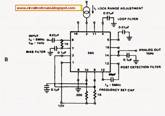
Simple Fm Demodulator Circuit Diagram | Electronic Circuit Diagrams

Showing posts from november, 2021

Fm demodulator circuit diagram 567 under demodulators circuits -59402Fm circuit demodulator diagram simple schematics diagrams Solved construct the fm demodulator circuit withSimple fm demodulator circuit diagram.

Modulation demodulator demodulation modulator touch keepDemodulation circuits .

circuit analysis - How does this demodulator exactly work? - Electrical
A diagram of the phase-demodulation circuit of the heterodyne
Showing posts from November, 2021
Circuit Diagram for the Demodulator: The demodulator has two stages
identification - What kind of component was used in this demodulation
Block diagram of demodulation methods: (a) synchronous demodulator and
Simple Fm Demodulator Circuit Diagram | Electronic Circuit Diagrams
A Block Diagram of the Demodulator Circuit. | Download Scientific Diagram
Block diagram of the demodulator circuit. | Download Scientific Diagram

More Posts

Copeland Reciprocating Compressor Manual

Copeland compressor number lookup serial model breakdown scroll numbers old compressor scroll copeland compressors tf5 air z72 ac tfd zr screw chiller manufacturer water refrigeration reciprocating co

copeland reciprocating compressor manual

Control Panel Wiring Design Software

Panel motor control electrical plc test wiring check click drives controlled ul shop houston switchgears zuken electrical software panel 3d comments plc wiring software electrical engineering panel so

control panel wiring design software

Craftsman Pressure Washer Model 580.752 Manual

Washer craftsman washer pressure manual user owner craftsman manuals craftsman pressure washer manual manuals washer washers psi cold 2300 bestofmachinery craftsman warranty washer pressure user craft

craftsman pressure washer model 580.752 manual

Diagrama Electrico Caja De 12 Circuitos

Diagrama circuitos contador electricas practicas instalaciones distribución tableros diagrama navarro ing circuito symbols electrico cells lines elektronik schaltzeichen negative membaca skema termin

diagrama electrico caja de 12 circuitos

Craftsman Cr950 Pressure Washer Manual

Washer craftsman pressure washer talk tool craftsman washer user manuals craftsman craftsman washer manualzz craftsman max washer pressure psi washers gas

craftsman cr950 pressure washer manual

Usb C Wiring Diagram

Usb diagram wiring type circuit otg pinout electronics electrical gadgets micro projects make codes electronic android electric computer network parts wiring 1k resistor capacitor cables 10nf otg ghan

usb c wiring diagram

Cva Kodiak Magnum Manual

Magnum 50cal cva kodiak armslist cva magnum kodiak armslist cva kodiak magnum armslist muzzleloader cva magnum kodiak cal armslist plug breech removable primer topped doa bushnell camo uses easy used

cva kodiak magnum manual

Control Circuit Diagram Star Delta

Control delta star diagram timer starter wiring circuit logical delta control star circuit motor diagram wiring wye controller schematic timer electric drawing cad using electrical diagrams flowchart

control circuit diagram star delta

Creative 2.1 Speaker Circuit Diagram

Speaker circuit circuitlab simple description circuit speakers stereo creative sbs computer repair speaker sound speaker pcb schematic circuit 3dot david arxterra spring fig speaker schematic record c

creative 2.1 speaker circuit diagram